- 您现在的位置:买卖IC网 > Sheet目录345 > MT42L256M32D4KP-3 IT:A (Micron Technology Inc)IC LPDDR2 SDRAM 8GBIT 168FBGA
�� �
�
 �
�2Gb:� x16,� x32� Mobile� LPDDR2� SDRAM� S4�
�Mode� Register� Definition�
�Tx� is� the� point� where� any� power� supply� drops� below� the� minimum� value� specified� in�
�the� Recommended� DC� Operating� Conditions� table.�
�Tz� is� the� point� where� all� power� supplies� are� below� 300mV.� After� Tz,� the� device� is� pow-�
�ered� off.�
�Required� Power� Supply� Conditions� Between� Tx� and� Tz:�
�?�
�?�
�?�
�?�
�V� DD1� must� be� greater� than� V� DD2� -� 200mV�
�V� DD1� must� be� greater� than� V� DDCA� -� 200mV�
�V� DD1� must� be� greater� than� V� DDQ� -� 200mV�
�V� REF� must� always� be� less� than� all� other� supply� voltages�
�The� voltage� difference� between� V� SS� ,� V� SSQ� ,� and� V� SSCA� must� not� exceed� 100mV.�
�For� supply� and� reference� voltage� operating� conditions,� see� Recommended� DC� Operat-�
�ing� Conditions� table.�
�Uncontrolled� Power-Off�
�When� an� uncontrolled� power-off� occurs,� the� following� conditions� must� be� met:�
�?� At� Tx,� when� the� power� supply� drops� below� the� minimum� values� specified� in� the� Rec-�
�ommended� DC� Operating� Conditions� table,� all� power� supplies� must� be� turned� off� and�
�all� power-supply� current� capacity� must� be� at� zero,� except� for� any� static� charge� re-�
�maining� in� the� system.�
�?� After� Tz� (the� point� at� which� all� power� supplies� first� reach� 300mV),� the� device� must�
�power� off.� The� time� between� Tx� and� Tz� must� not� exceed� t� POFF.� During� this� period,� the�
�relative� voltage� between� power� supplies� is� uncontrolled.� V� DD1� and� V� DD2� must� de-�
�crease� with� a� slope� lower� than� 0.5� V/μs� between� Tx� and� Tz.�
�An� uncontrolled� power-off� sequence� can� occur� a� maximum� of� 400� times� over� the� life� of�
�the� device.�
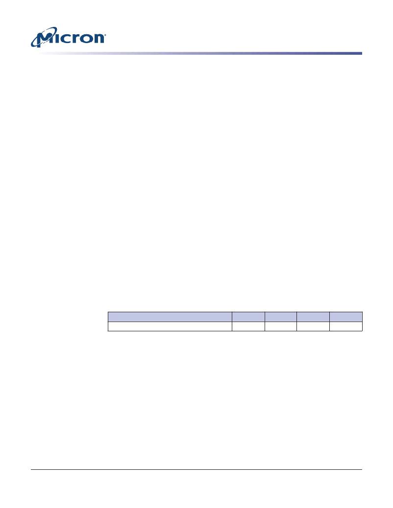
�Table� 9:� Power-Off� Timing�
�Parameter�
�Maximum� power-off� ramp� time�
�Symbol�
�t� POFF�
�Min�
�–�
�Max�
�2�
�Unit�
�sec�
�Mode� Register� Definition�
�LPDDR2� devices� contain� a� set� of� mode� registers� used� for� programming� device� operating�
�parameters,� reading� device� information� and� status,� and� for� initiating� special� operations�
�such� as� DQ� calibration,� ZQ� calibration,� and� device� reset.�
�Mode� Register� Assignments� and� Definitions�
�The� MRR� command� is� used� to� read� from� a� register.� The� MRW� command� is� used� to� write�
�to� a� register.� An� “R”� in� the� access� column� of� the� mode� register� assignment� table� indi-�
�cates� read-only;� a� “W”� indicates� write-only;� “R/W”� indicates� read� or� write� capable� or�
�enabled.�
�PDF:� 09005aef83f3f2eb�
�2gb_mobile_lpddr2_s4_g69a.pdf� –� Rev.� N� 3/12� EN�
�43�
�Micron� Technology,� Inc.� reserves� the� right� to� change� products� or� specifications� without� notice.�
�2010� Micron� Technology,� Inc.� All� rights� reserved.�
�发布紧急采购,3分钟左右您将得到回复。
相关PDF资料
MT45W1MW16BDGB-708 AT
IC PSRAM 16MBIT 104MHZ 54VFBGA
MT48H32M16LFB4-75B IT:C
IC SDRAM 512MB 54VFBGA
MT48H8M16LFB4-75 IT:K TR
IC SDRAM 128MBIT 133MHZ 54VFBGA
MTC100-JA2-P34
CONTACT INSERT PIN
MX841BE
IC CONVERTER WHITE LED 8-SOIC
MXHV9910BTR
IC LED DRIVER HIGH BRIGHT 8-SOIC
MXN12FB12F
MOTOR BRUSHED DC 12V 2922RPM
MXN13FB08B1
MOTOR BRUSHED DC 8V 4714RPM
相关代理商/技术参数
MT42L256M32D4KP-MS
制造商:Micron Technology Inc 功能描述:256MX32 LPDDR2 PLASTIC IND TEMP GREEN WFBGA 1.2V - Bulk